4.7 MW

650 MVA

9 MW

Power Factor Correction

Power Factor Correction

Find the MVAR needed to achieve a power factor of 99.8% .
The transformer rating is 650 MVA.
Easy to use: Click the white input box then enter new number. Or click the clear button then enter new number. Please remember if your input is in VA, then reactive power is in VAR
If your input is in kVA, then reactive power is in kVAR
If your input is in MVA, then reactive power is in MVAR.
Step 1. Click the clear button
Then enter VA or kVA or MVA . Next go to Step 2 enter desired power factor. Finally select button Solve, Q.
Given
VA or kVA or MVA

Step 2. Enter desired power factor in percent, do not enter the percent symbol
Desired Power factor in ( % ) = %
Var or kVar or MVar

Active Power =
Watt or kW or MW

Calculated VAR support needed to achieve the target power factor (If your input is VA) or
kVAR support needed to achieve the target power factor (if your input is kVA) or
MVAR support needed to achieve the target power factor (if your input is MVA)
To do scenario analysis, simply raise the target power factor and solve for the needed VAR or kVAR or MVAR support.
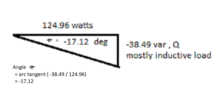
Angle Theta θ = °
Reactive Power Needed = plus or minus
Reactive power both capacitive and inductive is needed to create and maintain a changing magnetic flux for constant voltage transformation from high voltage for example 69,000 volts to 12,470 low voltage. Watch the video below about a constant 60 cyles per second changing magnetic flux to
induced a voltage in secondary winding to make voltage transformation possible.
LinkedIn shared lecture to demonstrate electro-magnetic induction principle
from Professor Walter Lewin
Shunt Capacitor, provides capacitive reactive power
Shunt Reactor, provides inductive reactive power
Voltage and Magnetic Flux directly proportional
Magnetic Flux and Current Characteristic Curve
Matlab Simulink of Reactor Energization
Static equipment such as static
synchronous compensators (STATCOMs) and static VAR
compensators (SVCs) [1] are now often used for reactive
power production. SVCs and STATCOMs have the advantage
of faster responses
Inductive and capacitive reactive power has zero average reactive power measured every 1 cycle sliding window or 2 pi or 6.28 radian
The reactive power is needed to maintain the alternating magnetic flux in order to create and maintain induced voltage and current to make voltage transformation possible.
Source: LinkedIn Post
I want to show the connection of fundamental principle about current leading the voltage in a sine waveform of a near perfect capacitive circuit. This time the connection is to leading power factor (p.f) as shown in a generator capability curve.
When you switch on or connect capacitors bank to improve the power factor to near unity power factor or 99.99% p.f. , you are importing VAR (KVAR, MVAR).
Utility operator uses the term VAR support (meaning they are going to switch on the capacitor circuit breaker). The leading power factor remember derives its meaning from current leading the voltage if you graph the voltage and current waveform measured
at capacitor terminal.
Negative power factor (- pf) is usually associated to inductive load exporting power and lagging power factor
Positive power factor (+ pf) is usually associated to capacitive load and importing power and leading power factor.
In power load flow analysis the power leaving the bus voltage node is associated to lagging power factor and designated by negative power factor (- pf)
while the power entering the bus voltage node is associated to leading power factor and designated by positive power factor (+ pf).
[Capability Curve] & [Voltage Stability Curve] for Synchronous Generators
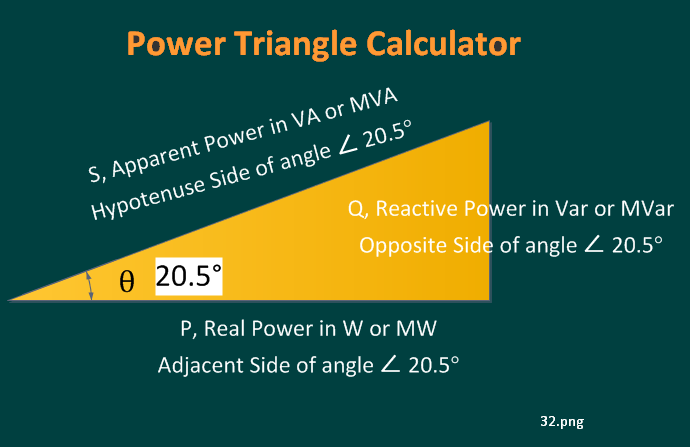
Formula Recall
S2 = P2 + Q2 ; Using Pythagorean Theorem
 Link to Parallel RLC circuit
IN-V-BAT-AI helps you recall information on demand—even when daily worries block your memory. It organizes your knowledge to make retrieval and application easier. 🔗
Source: How People Learn II: Learners, Contexts, and Cultures
Copyright 2025
Never Forget with IN-V-BAT-AI
INVenting Brain
Assistant Tools
using Artificial Intelligence
(IN-V-BAT-AI)
Since
April 27, 2009
April 27, 2009