.
 👈
👈


📱 Launch 504 Custom Educational Websites for Just $30/Year
No coding. No hosting. Just results.
Empower your classroom, tutoring service, or educational platform with 200 custom calculators and 304 math exam tutor sites—all hosted and maintained for you. That’s 504 personalized tools for just 6 cents each per year.
✅ Zero technical setup
Just email us what you want updated—we’ll handle the rest.
✅ Instant deployment
Your tools go live fast, optimized for mobile and voice search.
✅ Built for learning
Designed to support memory recall, personalized study, and exam prep.
🎯 Who It’s For
Teachers who want ready-to-use digital tools
Tutors scaling their services without tech overhead
Students needing reliable, on-demand study aids
Anyone who believes learning should be accessible and affordable
Never forget. Always be ready.
With IN-V-BAT-AI, your knowledge lives in the cloud—ready when you are.

IN-V-BAT-AI solution to forgetting! No coding. No website hosting.
Remember on demand is now possible!

Search this page Using AI - Voice to Text Keyword, Phrases or Number
Inductive Circuit Reviewer
 >
>
PURELY INDUCTIVE CIRCUIT LOAD
CURRENT PHASE ANGLE LAGS THE VOLTAGE PHASE ANGLE BY 90 DEGREE
From y-axis, vertical line, going to the right direction the voltage waveform (red) is leading the current waveform (blue) by 90 degree. Voltage is ahead by 90 degree to the current waveform. Another way of describing is the current is lagging or behind the voltage waveform by 90 degree

If a sine wave AC voltage source is applied to a purely inductive load, the current is at maximum when the voltage begins to rise from zero volt, and the current is zero when the voltage across the inductor is at maximum. The voltage lags 90° with the current by looking at the graph shown in the right. The current lags the applied voltage by 90° is another way of describing the dependency of current to the applied voltage in a purely inductive circuit.
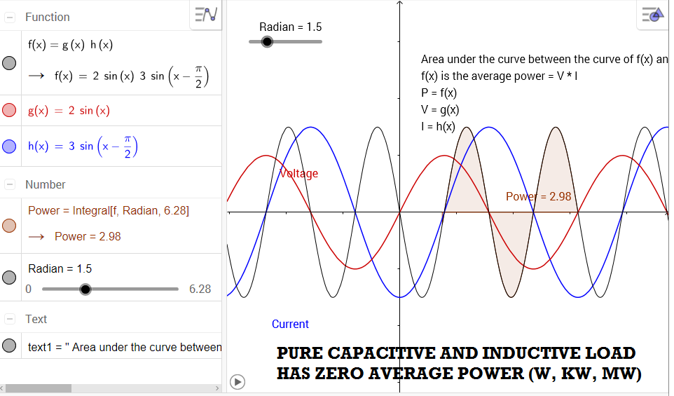
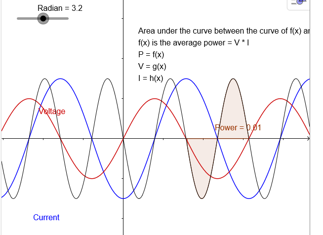
In a pure capacitive circuit load and pure inductive circuit load, the average power used (true power) is zero. Shown below is V-I Characteristic graph of a pure capacitive circuit. How can you tell if it is a pure capacitive circuit? Answer because the resulting current is leading the applied voltage by 90° Click the play button for animation showing the average power or average area under the curve is zero. Move the circle slider to 6.2832 radian or 2π
Credit to: Geogebra - Malin Christersson for sharing publicly: superposition of waves
Modified by Apolinario "Sam" Ortega for inductive circuit voltage, current, and power profile. Date created 7/9/2016
| At x = 0 | I = - 90 ° or - 1.5 radian | V = 0 ° |
| At x = 44 | I = 90 ° or 1.5 radian | V = 180 ° |
Source: LinkedIn Post
I want to show the connection of fundamental principle about current leading the voltage in a sine waveform of a near perfect capacitive circuit. This time the connection is to leading power factor (p.f) as shown in a generator capability curve.
When you switch on or connect capacitors bank to improve the power factor to near unity power factor or 99.99% p.f. , you are importing VAR (KVAR, MVAR).
Utility operator uses the term VAR support (meaning they are going to switch on the capacitor circuit breaker). The leading power factor remember derives its meaning from current leading the voltage if you graph the voltage and current waveform.
Negative power factor (- pf) is usually associated to inductive load exporting power and lagging power factor
Positive power factor (+ pf) is usually associated to capacitive load and importing power and leading power factor.
In power load flow analysis the power leaving the bus voltage node is associated to lagging power factor and designated by negative power factor (- pf)
while the power entering the bus voltage node is associated to leading power factor and designated by positive power factor (+ pf).
Visualizing the current flow in an inductor coil

Credit to : Chetvorno from Wikimedia Commons
Find the Active Power Transfer
Given sending voltage, Vs = 525 kV ; sending voltage phase angle theta, θ = 30°
receiving voltage, Vr = 520 kV; receiving voltage phase angle theta, θ = 20° Transmission line series reactance = 150 Ω

![]()
Units of sending voltage, Vs, = must be converted in kV
and
receiving voltage, Vr = must be converted in kV
Units of phase angle of sending voltage and receiving voltage must be in degree = °
Transmission line series reactance XL must be in ohms = Ω
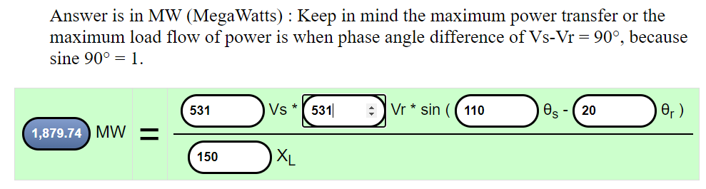
Answer is in MW (MegaWatts) : Keep in mind the maximum power transfer or the maximum load flow of power is when phase angle difference of Vs-Vr = 90°, because sine 90° = 1.
|
MW
| = |
Vs * Vr *
sin ( θs - θr )
XL
|
Using the active power transfer equation as your reference, how can you increase active power transfer?
Answer 1. To increase active power transfer install a phase shifting transformer at the receiving station. For example, using the above calculator , you install a phase shifting transformer at receiving station with phase angle of zero degree (0 °). What is the maximum possible MW of active power transfer?
Answer 2. To increase active power transfer install series capacitors at both ends of transmission, at the sending station and receiving station, using the above calculator, you install two series capacitors at both ends of transmission line such that the equivalent total impedance of transmission line and two shunt reactors is 100 ohms ( Ω ). What is the maximum possible MW of active power transfer?
Answer 3. To increase active power transfer raise the sending voltage to 530 kV at the sending station. For example, using the above calculator , you raise the sending voltage to 530 kV. What is the maximum possible MW of active power transfer?
Answer 4. To increase active power transfer you can use any combination of the first three answer.
How do you calculate the Surge Impedance Loading (SIL)?
Answer: Surge Impedance Loading (SIL) limit is calculated by multiplying the sending voltage and receiving voltage divided by the impedance of the transmission line. By looking at active power transfer equation, the maximum power transfer or the maximum load flow of power is when phase angle difference of Vs-Vr = 90°, because sine 90° = 1.
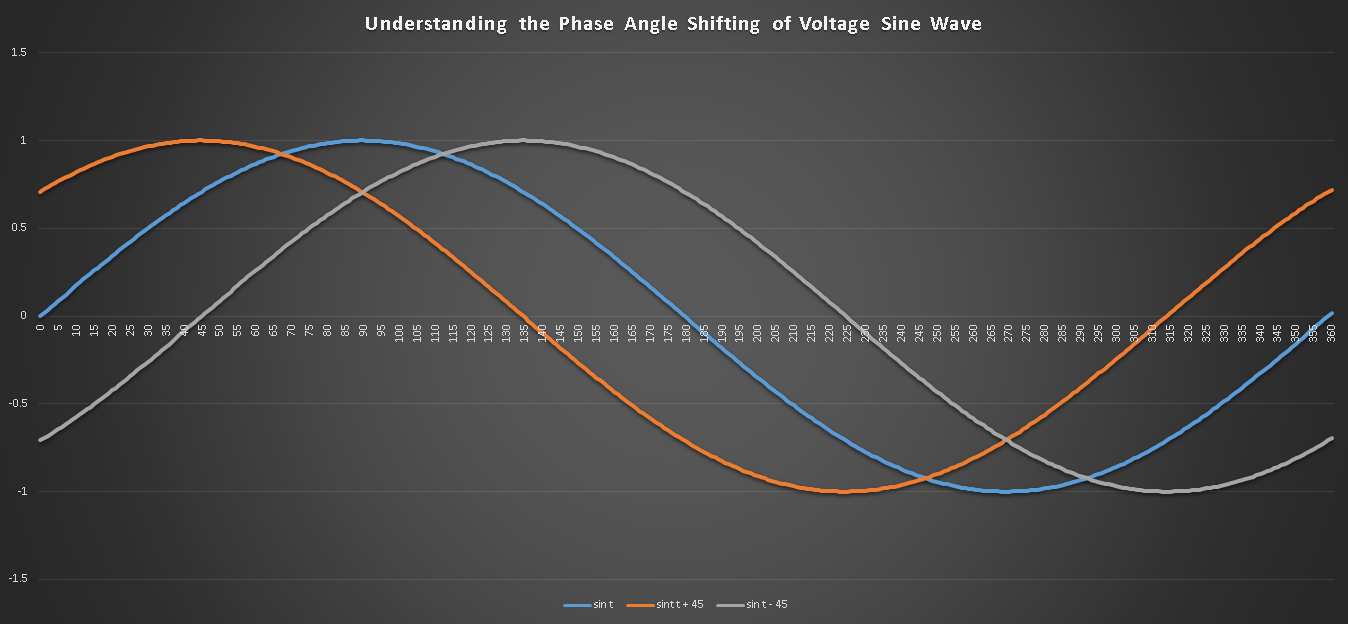
Blue sine waveform is the reference at 0°
As power flows along a transmission line, there is an electrical degree phase shifting, (easy to see by comparing the sine waveform of the sending voltage and receiving voltage) which increases with distance of transmission line and with power flowing in transmission line. As this electrical degree phase shifting increases, the transmission line become vulnerable during electrical disturbance (for example short circuit in transmission lines).
The massive Spain power blackout this year occurred on April 28, 2025. The official report on the Iberian blackout confirms it was mainly a voltage instability event.
How much knowledge and understanding have you collected about the importance of shunt reactor in a long transmission lines?
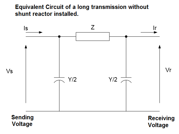
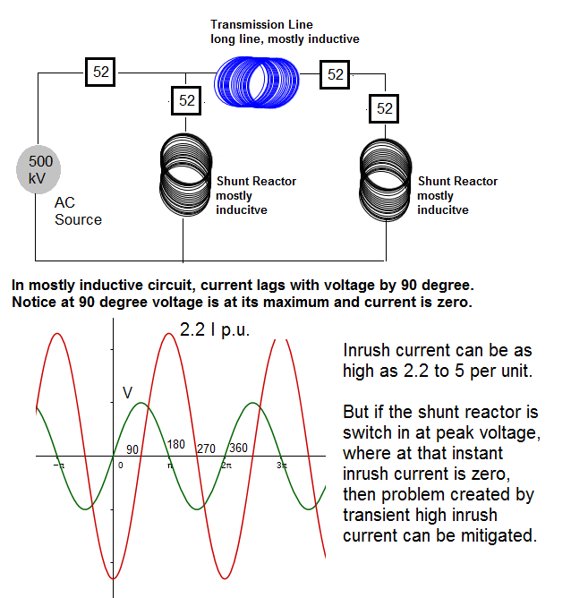
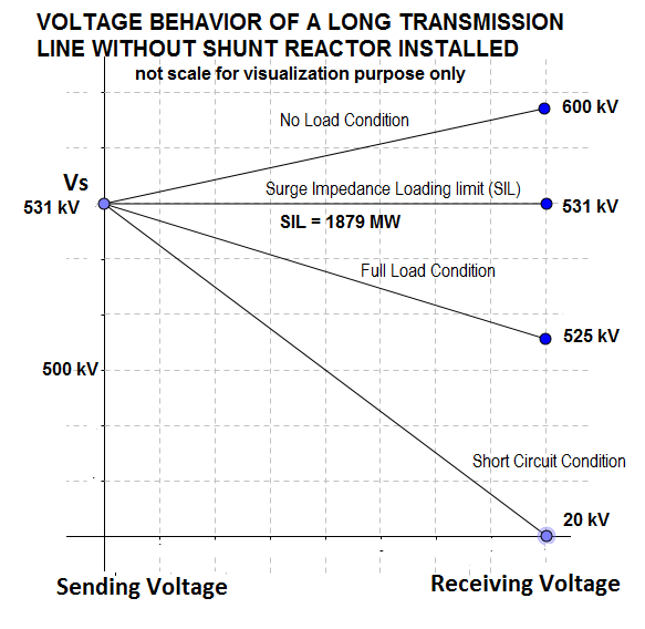
Shunt reactors are needed in a long transmission to regulate the voltage at the receiving station. By looking at the voltage characteristic graph shown below. The graph used straight line for visualization purposes only. If a long transmission line don't have shunt reactors, you will notice big problem in voltage regulation from no load condition, full load condition, and short circuit condition during disturbances in transmission line.
By installing shunt reactors , you are managing your transmission lines overvoltage condition during light load to no load that can exceed the maximum allowable operating limits of your apparatus such as power transformers and power circuit breakers .
However, shunt reactors should be removed from the transmission line during full load conditions. Why ? because it's impedance will be added to the transmission line impedance , hence more impedance to limit the active power flow. Refer to above power transfer equation component, XL . You see the higher your total equivalent transmission impedance, XL, your power flow transfer is lower. Use the calculator above and increase XL = 200. What happen to your power flow value?

So during months that the loads are light, shunt reactors are switch-in using device 52 or Power Circuit Breaker to prevent over voltages that can exceed the maximum allowable voltage limit of apparatus.
But during months that the loads are heavy, shunt reactors are switch-out or removed in order to allow for more power flow to supply the heavy load needed.
During the process of switching in , inrush current, a transient event related to magnetic flux saturation in the shunt reactor magnetic circuit (laminated steel core ) can create problem especially when the shunt reactor phase circuit is closed in at zero voltage. Why? Because at zero voltage, the inrush current is at maximum level. So where is the problem coming? At high value inrush current, the shunt reactor laminated steel cores that are designed to contain the magnetic flux generated by normal inrush current can get saturated with magnetic flux quickly during first half cycle (8.3 ms).

Here is the problem, when the laminated steel cores reaches it magnetic flux quota limit, there is no more resistance to the inrush current created during the switching in of shunt reactor and it will increase faster that can exceed the design limit of power circuit breaker and other apparatus.
So what is the solution to this problem? Remember the worst condition of inrush current can happen only at precisely zero voltage refer to the graph above. Furthermore the graph is also helping us to see that at precisely 90° , 270° or at exactly maximum voltage, generated current is zero (0) for all mostly inductive circuits like shunt reactors and long transmission lines. The solution therefore is to specify power circuit breaker (PCB)) that is designed to do switching of shunt reactor. This special PCB has the ability to precisely switch in consecutively each shunt reactor phase A, phase B, and phase C at peak voltage. So what is the importance of switching at the peak voltage? At the peak voltage there is no inrush current flowing or very limited inrush current. Therefore the magnetic circuit or laminated steel cores of the shunt reactor will not get saturated quickly.
What about removing the shunt reactor or switching out shunt reactor, is there any reported problem? Answer, if you specify the power circuit breaker designed for switching shunt reactor, then the switching out of shunt reactor is not a problem assuming all the timing circuitry of microprocessor related to switching logic are properly maintain to manufacturer specifications.
.
IN-V-BAT-AI helps you to remember on demand even if your memory recall is block by too much worries of daily life. It helps you to organize knowledge in ways that facilitate retrieval and easy to use immediately.
Source: How People Learn II: Learners, Contexts, and Cultures
.
How can IN-V-BAT-AI be used in classrooms ?
The IN-V-BAT-AI solution can be a valuable tool in classrooms, enhancing both teaching and learning experience. Here are some ways it can be utilized:
⋆ Personalized Learning : By storing and retrieving knowledge in the cloud, students can access tailored resources and revisit
concepts they struggle with, ensuring a more individualized learning journey.
⋆ Memory Support : The tool helps students recall information even when stress or distractions hinder their memory, making it
easier to retain and apply knowledge during homework assignments or projects.
⋆ Bridging Learning Gaps : It addresses learning loss by providing consistent access to educational materials, ensuring that
students who miss lessons can catch up effectively.
⋆ Teacher Assistance : Educators can use the tool to provide targeted interventions to support learning.
⋆ Stress Reduction : By alleviating the pressure of memorization, students can focus on understanding and applying concepts,
fostering a deeper engagement with the material.
.


.
.
Try AI website hosting
$30 per year
| Year | Top 10 countries | Pages visited |
| 2023 | 1. USA 2. Great Britain 3. Germany 4. Canada 5. Iran 6. Netherlands 7. India 8. China 9. Australia 10. Philippines | 127,256 Pages / 27,541 Visitors |
| 2024 | 1. USA 2. China 3. Canada 4. Poland 5. India 6. Philippines 7. Great Britain 8. Australia 9. Indonesia 10. Russia | 164,130 Pages / 40,724 Visitors |
| Daily Site Visitor Ranking 7/19/2025 | 1. USA 2. India 3. Canada 4. Iran 5. Latvia 6. Russia 7. Lithuania 8. Polan 9. Brazil 10. China | Year to Date 106,254 Pages / 32,111 Visitors |
Data source: Advanced Web Statistics 7.8