

subscribe to INVBAT.COM
Easy to use enter 154 or keyword Quadratic
Ready To Have Your Virtual Assistant - Click Here

sponsor ads
|
Buy online State Math Assessment practice test with explanation of the correct answer. Review anytime and anywhere to pass your State Math Assessment test for spring of 2018 |
Calculate 3-Phase Δ - Y Transformer
Symmetrical and Asymmetrical Available Fault Current

Calculate the base MVA maximum fault current using ANSI Method that would appear at the transformer bushing stud terminal. What is the base MVA internal winding fault current inside the tank on the high voltage coil or primary side of the transformer ? What is the 150 MVA internal winding fault current inside the tank? What is the 180 MVA internal winding fault current inside the tank? What is the 216 MVA emergency rating internal winding fault current inside the tank?
If the Digital Fault Recorder (DFR) Line to Ground Fault on Phase A recorded a fault of 3,850 A on the primary or high voltage side, did it exceed the emergency rating fault current? Explain your answer.
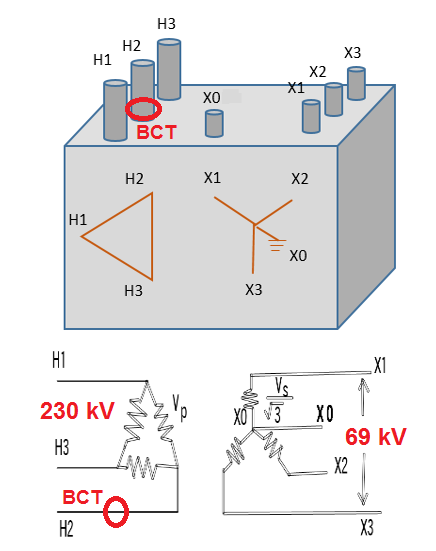
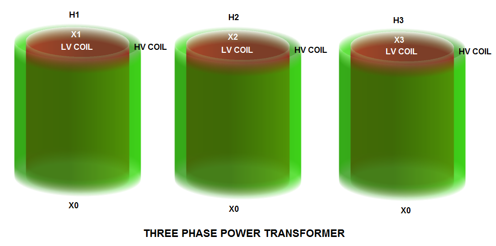
Given a 100 /150 / 180 MVA power transformer, 3 Phase 230/69 kV, delta-wye connection and has short circuit impedance of Z = 9.63%. The factory test report shows 100 MVA as the base MVA.
Next calculate the maximum fault current when this transformer is loaded at 150 MVA, 180 MVA and 216 MVA during emergency loading.


1 MVA = 1,000,000 VA ; 1 kV = 1000 V ; √3 = 1.732
Enter base MVA value and base kV value no need to do conversion. Answer is the base current in ampere.
|
Base current Line
Amp
| = |
3 Phase Base MVA
kV * 1.732
|
For secondary side available fault current calculation, change the primary voltage (230 kV) to secondary voltage (69 kV).
Section 7 of IEEE Std C57.12.00-2000 specified the general short circuit requirements for liquid-immerse distribution, power, and regulating transformers. For Category I and II transformers, symmetrical short circuit current shall be computed using transformer impedance only. For Category III and IV, system impedance should be included together with transformer impedance to calculate the symmetrical short circuit current. In our example our base MVA is 100 MVA, therefore it is a category IV transformer and should be calculated together with the system impedance. But for now we are neglecting the contribution of system impedance in our symmetrical short circuit calculation. By neglecting the system impedance, you are adding additional safety factor in your transformer short circuit withstand capability. In reality adding the system impedance will lower the calculated available short circuit current but it is difficult to get the real time transmission line impedance value because the network is dynamic due to power flow changes, unplanned outages due to storm and planned outages for scheduled apparatus maintenance.
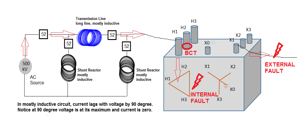

Do a simulation by adding a transmission line impedance to transformer short circuit impedance. What happen to the available short circuit current ?
In using this calculator to make decision if the transformer is operated within its factory % Z limit on short circuit withstand capability, you should remember to deduct some values of short circuit current dissipated by the transmission impedance in series with your transformer.
Next, very important to remember that digital fault recorder(DFR), fault current values are based on line current because the bushing current transformer (BCT) is its source of current signal which is measuring the line current. If the transformer WINDING is connected in WYE , then the line current of DFR and the transformer coil winding current are the same. But if the transformer WINDING is connected in DELTA, you need to divide the DFR fault current by square root of 3 , which is 1.732.
Then you make your comparison between actual DFR fault current vs transformer winding short circuit specified withstand capability based on its % Z from factory test.
| Category | Single Phase kVA | Three Phase kVA |
|---|---|---|
| I | 5 to 500 | 15 to 500 |
| II | 501 to 1667 | 501 to 5000 |
| III | 1668 to 10000 | 5001 to 30000 |
| IV | Above 10000 | Above 30000 |
Using the ANSI method the maximum available fault current at the transformer bushing stud terminal will be:
This is valid for WYE primary winding configuration because the line current is equal to the winding current.
|
Base MVA Available Fault Current Line
Amp
| = |
base current
base Z %
|
Now assuming the system impedance Zsys = 5 % is in series connection with transformer impedance. Therefore the total impedance, Ztotal = Ztr 9.63 % + Zsys 5 % = 14.63 %. The base short circuit current will be going down to 1715.851 Amp.
Transformer must also withstand the peak asymmetrical short circuit current
during the first cycle equivalent to 16.67 millisecond. ANSI method for calculating the peak asymmetrical short circuit current = K * Isc.
If the x/r ratio of the system is unknown. ANSI method indicates the x/r ratio of the transformer should be used. Assuming the the x/r ratio of the given 100/150/180 MVA power transformer is 25. Calculate the peak assymetrical short circuit current the given transformer must be able to withstand during the first cycle. From IEEE C57.12.00-2000 Table 7B-1 for x/r = 25
use K =
Therefore the peak asymmetrical line short circuit current
x
= Amp. Keep in mind, this value was based on x/r = 25. You must change your K-factor value depending on the transformer x/r value that you are analyzing.
For delta connected primary winding, the winding fault current = transformer terminal stud line fault current divided by square root of three or 1.732
This is valid for DELTA primary winding configuration because you need to divide the line current by 1.732 to get the winding current in a transformer that is delta connected.
|
Base MVA Available Fault Current Winding
Amp
| = |
Base MVA Max. Fault Current
|
Therefore the base MVA peak asymmetrical winding short circuit current for delta winding is
x k factor = Amp. Keep in mind, this value was based on x/r = 25. You must change your K-factor value depending on the transformer x/r value that you are analyzing.
HOW TO USE: Enter new number on any white input boxes shown below. Answer is automatic.
For scenario analysis: change the % Z value and the K - Factor value
When you change %Z or K-factor or both you should click all the white input boxes below to do new calculation base on new changes that you have made.
SUMMARY OF FAULT CALCULATION
Using default X/R = 25 therefore use K-factor = 2.662
If you change your K-factor or %Z value , you should recalculate by clicking all the white input boxes shown below.
| MVA RATING | LOAD Current | WYE-Fault Current | WYE-Assy. Fault Current | DELTA -Fault Current | DELTA -Assy. Fault Current |
>
?
Is the analysis correct? Why or Why not?
The above inequality equation is an example of DFR fault current interpretation for delta connected primary coil winding. Here the assumption is 200 A fault current reduction due to transmission lines impedance. Then comparing this value to emergency MVA rating available fault current to make your fault current analysis. One of the questions you may want to know the answer in your fault current analysis, is the actual fault current enough to cause your transformer to fail?
Did your transformer fail at this fault current? Knowing the answer to this question will maybe lead you to update your fault current studies for the substation. Maybe you need to update your % Z of your transformer specifications for the substation to mitigate the problem or add series reactor to limit the fault current.
How do we interpret the two (2) second short circuit withstand capability of the transformer? This will be my next topic for research.
IEEE C57.12.00-2000 Table 7 B-1 Values of K
X/R of a Transformer
| x/r | K |
|---|---|
| 200 | 2.806 |
| 167 | 2.802 |
| 143 | 2.798 |
| 125 | 2.793 |
| 111 | 2.789 |
| 100 | 2.785 |
| 50 | 2.743 |
| 33.3 | 2.702 |
| 25 | 2.662 |
| 20 | 2.624 |
| 16.7 | 2.588 |
| 14.3 | 2.552 |
| 12.5 | 2.518 |
| 11.1 | 2.484 |
| 10 | 2.452 |
| 5 | 2.184 |
| 3.33 | 1.990 |
| 2.5 | 1.849 |
| 2 | 1.746 |
| 1.67 | 1.669 |
| 1.43 | 1.611 |
| 1.25 | 1.568 |
| 1.11 | 1.534 |
| 1.0 | 1.509 |
4 Transformer Bank Fault Simulation Calculator Zero Current Crossing
Quick Estimate of Short Circuit Current Using Voltage Drop

